

Description
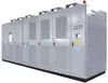
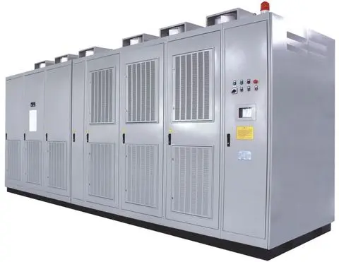
Product Features: High-Voltage Direct Power Supply: The DLHVF high-voltage variable frequency speed controller features direct high-voltage input and output, eliminating the need for an output step-up transformer. This results in a small footprint and suitability for ordinary AC induction motors. High Efficiency: The DLHVF high-voltage variable frequency speed controller boasts an efficiency of over 96%. High Power Factor: The DLHVF high-voltage variable frequency speed controller achieves a power factor of over 0.95. Harmonic-Free Input: The DLHVF high-voltage variable frequency speed controller utilizes phase-shifting multi-stage rectification technology at the input, resulting in low voltage and current harmonics. No additional harmonic mitigation devices are required at the input, preventing pollution to the power grid. Harmonic-Free Output: The DLHVF high-voltage variable frequency speed controller outputs a standard sinusoidal current with low voltage and current harmonics. No additional harmonic compensation devices are needed at the output, preventing increased motor noise and additional stress. High Reliability: The DLHVF high-voltage variable frequency speed controller features automatic fault bypass and high-voltage power-off restart functions, ensuring uninterrupted motor operation even in the event of a fault. High Safety: The DLHVF high-voltage variable frequency speed control device is designed in accordance with national mandatory standards for high voltage. Fiber optic connections are used between the high-voltage main circuit and the control circuit, ensuring safety and reliability. Comprehensive Protection and Fault Alarm Design: The DLHVF high-voltage variable frequency speed control device is equipped with complete system protection functions and power unit protection functions. After various protection actions, it can automatically record faults and remember accidents. The fault record can automatically record the action type and action time of various protections, which can help technicians analyze the cause of the fault and locate the fault. High Flexibility: The DLHVF high-voltage variable frequency speed control device is controlled on-site by a PLC. Parameter settings can be modified through a human-machine interface to flexibly change the control mode. It has multiple standard communication protocols for easy communication with the central control system. Convenient Installation, Debugging, and Maintenance: The power unit is designed in a drawer-like manner, and the power unit and external wiring use a plug-in method, eliminating the need for manual wiring and providing good interchangeability for easy replacement. Unique Technical Features: 1) Adaptive Waveform Digital Synthesis: The waveform generation section of the DLHVF high-voltage frequency converter uses a single FPGA to obtain discretized three-phase waveform data with controllable frequency and amplitude through a certain algorithm. This data is then compared with triangular carrier waves of different phases to generate waveform data signals that control the output of the fundamental voltage with the same amplitude and phase of the same phase power unit. However, the carrier waves of each unit in series are staggered by a certain electrical angle to achieve multi-level superimposed waveforms, which greatly improves the reliability of the overall control system. 2) Low-Voltage Unit Debugging Function: The DLHVF high-voltage frequency converter can use a low-voltage control power supply to perform functional tests on the high-voltage frequency converter. Users can debug and maintain the high-voltage frequency converter online when there is no high-voltage power supply or when the motor is running at its power frequency, which greatly shortens the debugging and maintenance time of the high-voltage frequency converter equipment. 3) Advanced Automatic Fault Detection Technology: Before each startup, the DLHVF high-voltage frequency converter automatically performs online testing on the entire system and each power unit. Power unit testing can be specific to the performance of each IGBT, ensuring the entire device is in good working order before startup and making preparations more organized. 4) Power Units Adopt Drawer-Type Structure for Easy Replacement and Maintenance: The connections between the power units and the main circuit on the DLHVF high-voltage frequency converter power cabinet are all via moving and stationary contacts. Installation and removal only require removing two optical fibers, eliminating the need for strenuous disassembly of the main circuit bolts. Furthermore, all main circuit connections are located at the rear of the cabinet, ensuring personnel safety. 5) Online Power Unit Switching: During normal operation, the DLHVF high-voltage frequency converter allows manual switching of any power unit. Power units that were bypassed due to interference can be manually switched back into normal operation. Since most faults in high-voltage frequency converters are caused by interference, this function significantly improves the mean time between failures (MTBF) of the high-voltage frequency converter, thus enhancing its reliability. 6) Online DC Voltage Detection Function for Power Units: The DLHVF high-voltage frequency converter monitors the DC bus voltage of each power unit online under high-voltage conditions and displays the measured values on the human-machine interface. This allows operators to intuitively grasp the operating status of the main circuit of each power unit, providing a strong guarantee for further analysis. 7) Power Unit Soft Bypass Function: The DLHVF high-voltage frequency converter employs a combination of mechanical and electronic bypass when a power unit malfunctions, ensuring the reliability of automatic bypass. 8) Instantaneous Torque Control Function: Under process conditions with sudden load changes, instantaneous torque control is implemented to prevent the high-voltage frequency converter from tripping due to overcurrent or instantaneous tripping, improving equipment reliability. 9) Variable Frequency Soft Start Control Technology: The starting current of the variable frequency start is small, there are no requirements for the number of starts, and it can seamlessly switch to power frequency operation after start-up without current surges. 10) Motor Rotation Restart Control Technology: Its key feature is that in the event of motor stall, the high-voltage frequency converter can automatically identify the motor speed and engage without disturbance, driving the motor to frequency conversion operation. The main circuit of the DLHVF series high-voltage frequency converter generates high voltage by superimposing the outputs of multiple low-voltage power units. The low-voltage power units are improved and optimized standard low-voltage PWM (Pulse Width Modulation) low-voltage motor frequency converters, which have been widely used for many years. Figure 1 above shows a typical circuit topology of the DLHVF series high-voltage frequency converter. For a 6kV frequency converter, each phase of the motor is driven by 5 to 6 power units connected in series, totaling 15 to 18 power units that can generate a 6000V AC line voltage. For a 10/11kV frequency converter, each phase of the motor is driven by 8 to 9 power units connected in series, totaling 24 to 27 power units that can generate a 10000~11000V AC line voltage. The power units are connected in a star configuration with the neutral line floating. Each power unit is powered by the isolated secondary winding of an isolation transformer, receiving a three-phase 690V AC, 50/60Hz power input, and an inverter output of a variable power supply with a maximum voltage of 750V AC and a maximum frequency of 120Hz. The power unit, its corresponding transformer secondary winding, and its insulation level to ground are designed for 6kV or 10kV/11kV high-voltage levels. All power units receive commands from the same main control unit controller. These commands are transmitted via fiber optic cable to ensure high-voltage and low-voltage isolation. A typical power unit schematic is shown in Figure 2 above. A three-phase diode rectifier powered by the 690VAC secondary charges the DC capacitor bank to approximately 1000VDC, which is then supplied to a single-phase H-bridge inverter circuit composed of IGBTs. The phase-shifting transformer secondary windings supplying power to the power units are wound with a certain phase difference between each other. Each phase of 5 or 6 power unit main circuits can form a 30 or 36-pulse rectification mode. Each phase of 8 or 9 power unit main circuits can form a 48 or 54-pulse rectification mode. This multi-stage phase-shifting superposition rectification method enables the DLHVF series high-voltage variable frequency speed control unit to generate an output waveform very close to a sine wave. This eliminates most of the harmonic currents caused by independent power units, so the current drawn from the grid is also approximately a sine wave. The THD of the input current of the DLHVF series high-voltage variable frequency speed control unit is also kept below 3%. At rated output power, the waveforms of the motor voltage and current of the DLHVF series high-voltage variable frequency speed control unit are very accurately close to true sine waves. The quantitative measurement of waveform quality is its total harmonic distortion, i.e., THD. The THD of the motor current using the DLHVF series high-voltage variable frequency speed control unit is less than 3%. The control system of the DLHVF series high-voltage variable frequency speed control unit consists of a main control unit and a PLC (optional). The main control unit consists of a power supply board, a sampling board, and I/O and logic boards, and the main control board and three fiber optic interface boards. The sampling board detects input and output signals, performs range conversion and filtering, and then sends the signals to the main control board via the motherboard. The core components of the main control board consist of ARM and FPGA, which analyze and process the signals, and control, trigger, block, and bypass IGBTs for each power unit, enabling the frequency converter to provide the corresponding frequency and voltage output. The I/O and logic board (PLC) receives user control commands (start, stop, emergency stop, frequency setting, etc.) and performs various switching signal logic processing. The control system also monitors the status of various components of the frequency converter (such as each power unit, transformer, fan, etc.), provides fault diagnosis information, and realizes fault alarm and protection. In field applications, the control system can achieve flexible interface with the field, providing control functions required by the field such as valve linkage and automatic scheduling, and easily changing the control mode to meet the special requirements of the user's field. The bypass device is used to switch from frequency conversion to mains frequency operation when the high-voltage variable frequency speed control device malfunctions due to a major fault. There are two types: manual and automatic bypass devices. Users can choose the option based on their specific requirements. The standard configuration of the high-voltage variable frequency speed control device does not include a bypass device. The manual bypass device consists of a high-voltage disconnect switch. For frequency conversion operation, QS2 should be disconnected first, then QS1 should be closed. For mains frequency operation, QS12 should be disconnected first, then QS2 should be closed. When switching between frequency conversion and mains frequency operation, the disconnect switch must be manually closed and opened only after the motor has completely stopped. It is forbidden to close or open the disconnect switch while it is energized. The automatic bypass device consists of a high-voltage contactor. For frequency conversion operation, KM3 should be disconnected first, then KM1 and KM2 should be closed. For mains frequency operation, KM1 and KM2 should be disconnected first, then KM3 should be closed. The system automatically switches the opening and closing of the high-voltage contactor when switching between frequency conversion and mains frequency operation. Technical Specifications | Item | Description | Standard Used | Q/XDL J01-013-2018 | Installation Location | Indoor cabinet-mounted | Topology | Power unit multi-level series PWM voltage source | Rectification Form | Phase-shifted multi-pulse | Motor Requirements | Ordinary high-voltage motor | No requirement | Input Filter | Not required | Output Filter | Not required | Input-side fuse protection | Yes | Power unit input fuse protection | Input Voltage | -30%~+15% of rated voltage, frequency 45Hz~55Hz | Voltage drop below 15% during derating operation | High-voltage input current harmonic content < 4% | High-voltage input power factor >0.96 | High-voltage output voltage and current harmonic content < 4% | High-voltage output side frequency | 5~120Hz, resolution 0.01 Hz | High-voltage output voltage | 0~rated voltage, voltage fluctuation rate ± 0.5% | Overload Capacity | 1.2 times 1min, 1.5 times immediate protection | Special requirements can be made | Overall device efficiency | Full load > 97%, other loads > 96% Reliability Indicators (Mean Time Between Failures): 25,000 hours; Control Power Supply: Three-phase four-wire AC 380V, 5kVA capacity; High and Low Voltage Control Signal Connection: Fiber Optic Cable; Noise Level: <75dBA (at 1 meter); Protection Rating: ≥IP30; Cooling Method: Forced Air Cooling; Standard Control Connections: RS485, MODBUS RTU; Standard Industrial Communication Interface: Analog Signal (Input) Specifications and Quantity: 4-20mA or 0-10V, 1 channel; Expandable Analog Signal (Output) Specifications and Quantity: 4-20mA or 0-10V, 2 channels; Expandable Switch Signal (Input) Specifications and Quantity: 7 points; Expandable Switch Signal (Output) Specifications and Quantity: 220VAC, 5A, 10 points; Expandable Operation Method: Touch Screen; Interface Language: Full Chinese; Language can be switched upon request; Grounding Requirements: Grounding Resistance <1Ω; Normal Operating Conditions: Minimum ambient temperature 0℃, maximum ambient temperature 40℃, temperature variation of the operating environment should not exceed 5℃/h. If the ambient temperature exceeds the permissible value, appropriate air conditioning equipment should be considered; Ambient humidity should be less than 90% (20℃), and the relative humidity change rate should not exceed 5% per hour to avoid condensation; The installation height should be less than 1000 meters above sea level. If the installation height exceeds 1000 meters above sea level, the equipment must be used at a reduced capacity, or ventilation measures should be adopted, or a special design can be made; The installation should be carried out in a non-explosive medium, and the medium should not contain gases or dust that could corrode metals or damage insulation.
- Soft starter
- frequency converter
- variable frequency speed control
- motor control
- VFD
Production Capacity:
Not informed
Delivery Timeframe:
Not informed
Incoterms:
CFR - Cost and Freight
CIF - Cost, Insurance and Freight
EXW - Ex Works
FCA - Free Carrier
FOB - Free on Board
Packaging Details:
出口海运包装
More about
Big Pawer Electrical Technology Xiangyang Inc. Co., Ltd.
200-500
Employees
10M - 50M
Sales volume (USD)
10%
% Export sales
Year
Established
Business type
- Industry / Manufacturer
Keywords
- Soft starter
- frequency converter
- variable frequency speed control
- motor control
- switch cabinet
- control cabinet Ver Mais
Contact and location
-
 WJ ********
-
+86 8********
-
Xiangyang / Hubei | China
