

Description
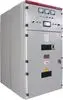
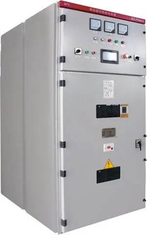
1. Overview The MPS1 high-voltage solid-state soft starter system comprises components such as thyristor assemblies, bypass contactors, trigger control systems, and protection systems. It features a compact structure, comprehensive functions, high reliability, and small size. The working principle of this soft starter is to control the output voltage by controlling the firing angle of the thyristors, meeting the different current and voltage requirements during motor starting. During motor starting, the MPS1 high-voltage solid-state soft starter increases the motor's terminal voltage according to a pre-set starting curve, allowing the motor to accelerate smoothly, thereby reducing the electrical and mechanical impact on the power grid, the motor itself, and the motor load during starting. Once the motor reaches normal speed, the bypass switch is activated, and the motor starting is complete. 1.1 Main Applications and Scope of Application The MPS1 high-voltage solid-state soft starter is mainly used for step-down soft starting of various large and medium-sized high-voltage motors. Scope of application: Voltage range: AC3.0-15kV; Power range: 200kW-10000kW; Frequency: 50Hz/60Hz±2 Hz; Motor type: Three-phase high-voltage AC motor or asynchronous starting synchronous motor. 1.2 Composition and significance of the model 1.3 Model and specifications Table 1-1 provides parameter descriptions for different models of soft starters. Table 1-1 Parameter Description of Different Soft Starter Models | Soft Starter Model | Rated Voltage (kV) | Compatible Motor Power (kW) | Dimensions (mm) | Weight (kg) | Width (W) | Depth (D) | Height (H) | |---| ... 2000 1000 1500 2300 800 MPS1-2500/6 6 2500 1400 1600 2300 900 MPS1-3150/6 6 3150 1400 1600 2300 950 MPS1-4000/6 6 4000 1600 1650 2300 1100 MPS1-5000/6 6 5000 1600 1650 2300 1100 MPS1-6300/6 6 6300 1600 1700 2300 1200 MPS1-500/10 10 500 1000 1500 2300 750 MPS1-710/10 10 710 1000 1500 2300 750 MPS1-1000/10 10 1000 1000 1500 2300 750 MPS1-1250/10 10 1250 1000 1500 2300 750 MPS1-1600/10 10 1600 1000 1500 2300 750 MPS1-2000/10 10 2000 1000 1500 2300 850 MPS1-2500/10 10 2500 1000 1500 2300 850 MPS1-3150/10 10 3150 1000 1500 2300 950 MPS1-4000/10 10 4000 1400 1650 2300 950 MPS1-5000/10 10 5000 1400 1650 2300 950 MPS1-6300/10 10 6300 1600 1700 2300 1150 MPS1-7100/10 10 7100 1600 1700 2300 1150 MPS1-8000/10 10 8000 1600 1700 2300 1250 MPS1-9000/10 10 9000 1600 1700 2300 1250 MPS1-10000/10 10 10000 1600 1700 2300 1450 Note: For motors with higher power or special dimensions, please contact our company. 1.4 Environmental Conditions Ambient temperature: upper limit not exceeding 40℃ (24-hour average temperature not exceeding 35℃), lower limit not lower than -15℃; Relative humidity: not exceeding 95%; Altitude: not exceeding 1500m, capacity should be reduced above 1500m; Should be placed indoors, in a place free from severe vibration and impact, and without fire or explosion hazards; Not exposed to direct sunlight, corrosive gases, flammable and explosive gases, water vapor, oil mist, dripping water, dust, metal particles, conductive dust, or places with severe vibration. 2. Structural Features and Working Principle 2.1 Overall Structure and its Working Principle and Characteristics 2.1.1 Overall Structure The MPS1 high-voltage solid-state soft starter adopts a cabinet structure with bottom-entry and exit wiring. During wiring, simply connect the high-voltage solid-state soft starter in series between the high-voltage motor and the high-voltage switchgear. Please contact us for a detailed wiring diagram. Note: When the high-voltage operating cabinet is integrated with the user's high-voltage cabinet, a side-entry wiring method is generally used. The specific wiring method is subject to the actual design. The MPS1 high-voltage solid-state soft starter mainly includes thyristor modules, bypass contactors (or vacuum circuit breakers), overvoltage protectors, current transformers, voltage transformers, electronic control systems, and other components. The internal structure of this device is simple, with modular components, making maintenance simple and convenient. Please contact us for a detailed external drawing. Figure 2-2 Schematic diagram of thyristor soft starter cabinet. Note: The left is the high-voltage switchgear, and the right is the high-voltage soft starter device. 2.1.2 Working principle: The soft starter triggers the thyristor based on the detected voltage signal and preset parameters, and the output voltage gradually increases, thereby reducing the terminal voltage and starting current of the motor during startup, allowing the motor speed to gradually and smoothly increase to the rated speed. When a decrease in current is detected, it automatically switches to bypass, thus realizing the soft start of large and medium-sized motors. Its principle block diagram is shown in Figure 2-3. Figure 2-3 Block Diagram of High-Voltage Solid-State Soft Starter 3. Technical Characteristics Rated Voltage 3kV, 6kV, 10kV Standard GB/T27405-2019 Motor Type Three-phase squirrel-cage motor or wound-rotor motor, asynchronous starter synchronous machine Rated Operating Frequency 50HZ/60HZ±2HZ Control Power Supply AC220V ±10% Operation Panel Touchscreen Cooling Method Natural cooling Number of Start-ups 1-5 times per hour Interval between starts: 0-300s Protection during Start-up Overcurrent protection, overvoltage protection, undervoltage protection, current imbalance protection, start-up timeout protection, bypass vacuum switch opening/closing fault detection; Starting Method Ramp-up start, time-limited start, constant current start, soft stop control Soft start time 0~100 seconds adjustable Soft stop time 0~60 seconds adjustable Output Voltage 20%~100% adjustable (adjustment method is to change the trigger time) Constant Current Multiple 1Ie~5Ie adjustable communication interface, RS-485 communication interface, default support for Modbus protocol, Profibus optional. Ambient temperature: Operating: -15℃~+40℃, Storage: -25℃~+70℃; Ambient humidity: ≤95% non-condensing; Altitude requirement: ≤1500m. 4. Installation and Commissioning 4.1 Equipment Installation Conditions Determine the equipment placement space according to the engineering design; excavate cable trenches according to the selected equipment, and treat the surface of the cable trenches with cement to ensure their reliability and durability; Set up embedded parts, and set up the necessary embedded parts according to the equipment layout drawing; Prepare primary cables and secondary cables between control cabinets according to design requirements; Clean the equipment space before installation and ensure that the space is dry; Cable testing: Check the diameter of each cable, compare it with the cable factory report, and conduct relevant tests. Please refer to relevant national standards. 4.2 Installation Precautions When positioning the equipment, pay attention to using the correct hoisting and transportation methods; ensure that the cable interface is above the cable trench for easy cable installation; The equipment can be fixed with anchor bolts or welded to the fixed foundation channel steel; Determine the connection method for the primary and control cables; the supplier should provide a pipeline table; Position the primary and control cables according to the pipeline table; After the wiring is completed, seal the exposed cable trench to prevent debris from falling into the cable trench. 4.3 Inspection and Confirmation Items 4.3.1 Confirm that the cable installation is correct. The motor wiring is connected to the connectors marked U, V, W in the starter cabinet. The phase sequence must correspond accurately, and the connectors should be wrapped with high-voltage insulating heat shrink tubing. 4.3.2 Confirm that the control wiring is correct. Please contact us to obtain a detailed control wiring diagram. Lead the ground wire from the grounding post of the cabinet to the on-site grounding busbar. The grounding cable should be as short as possible and connected to the nearest grounding point next to the soft starter cabinet. 4.4 Preparations Before Trial Operation 4.4.1 Before powering on, please perform the following checks in the following order: Check for loose installations of electrical and mechanical components, and for the presence of metal shavings and fragments inside the cabinet. Perform insulation resistance measurement and power frequency withstand voltage test as described in Section 4.5.1; perform low-voltage bulb test as described in Section 4.5.3. Check that the motor wiring is connected to the output terminals U, V, and W of the MPS1 soft starter, and that the phase sequence is correct. Check that the external terminal signals are connected as required by the design, and check that the system grounding is good. Check that the pointers of the motor ammeter, mains voltmeter, and motor voltmeter on the panel are at zero. If not, manually adjust them to zero. Check that the control power supply is AC220V and that its wiring is correct. Connect the external control power supply, close the 220V control power supply circuit breaker, the power indicator light will illuminate, the touch screen will illuminate, and the start-permit indicator light will illuminate. • Check the parameters displayed on the LCD screen. If necessary, make corrections. Please refer to the detailed instructions in Chapter 6, "Parameter Settings." It is recommended to use the factory-set parameters for trial operation. Pay special attention to whether the motor's rated current setting is correct. 4.4.2 Initial Parameter Settings The motor starts under rated load. The starting method is selectable. In constant current starting mode, the motor starting current can be effectively limited to achieve ideal starting effect. 4.4.3 Parameter Settings The following table shows the parameter settings for the MPS1 soft start touchscreen, as shown in Table 4-2: Soft Start Parameters: Default Soft Start Mode Settings Ramp-up/Constant Current/Constant Time Constant Time Starting Voltage (%) 10~50 26 Starting Time (s) 10~100 60 Constant Current Multiple (%) 1~500 350 Jump Voltage (kV) 0~10.0 7.0 Jump Delay (s) 0~2.0 0.0 Stop Time (s) 0~100 0 Soft Stop Start Trigger Angle (%) 10~100 40 Soft Stop Stop Trigger Angle (%) 10~100 60 Advanced Soft Start Parameters: Constant Current Coefficient K1 3-5 4 Constant Current Coefficient K2 1-5 1 Constant Current Coefficient K3 2-5 2 Constant Current Coefficient K4 System Parameters: Rated Current (A) 0~1000 57 Voltage Ratio (kV/100V) 3~10 10 Current Ratio (A/5A) 0~4000 300 Modbus Station Number 1-255 1 Baud Rate 1200,2400,9600,19200 9600 Protection Parameters: Upper Current Limit (A) 0~5000 500 Current Imbalance Limit % 10~100 50 Forced Switching Time (s) 0~60 60s Upper Voltage Limit (kV) 0-15.0 13.0 Lower Voltage Limit (kV) 0-10.0 4.0 Starting Overfrequency Interval (min) 0-10 5 Undercurrent Protection Time (ms) 0-9999 5000 Thermal capacity protection coefficient X1 0-9999 2 Thermal capacity protection coefficient X2 0-9999 1 Upper temperature limit (°C) 0~100 35 Upper phase comparison limit 0~65535 8000 Lower phase comparison limit 0~65535 6600 4.4.4 Explanation of main parameters Soft start parameters: Starting voltage parameter name Factory setting Unit Range Starting voltage 26 % 10~50 When set to 21, it indicates that when the thyristor is initially triggered to conduct, the equivalent voltage output by the device is the voltage corresponding to a 21% conduction angle. The larger the starting voltage setting value, the higher the starting voltage and the larger the initial starting current. It is generally recommended not to exceed 30%. Soft start time parameter name Factory setting Unit Range Starting time 60 s 10-60 The maximum soft start time for the motor. If the system determines that the motor has fully started but the set time has not yet been reached during the starting process, the system will automatically switch to full voltage, and the motor will run at full voltage. If the motor has not started within the set soft start time, the soft starter will trip, and the touch screen will display a start timeout. Constant Current Multiple Parameter Name Factory Setting Unit Range Constant Current Multiple 350 % 1.0-5.0Ie The minimum setting is 1.0Ie, limiting the starting current of the soft starter to the set range. Jump Voltage Parameter Name Factory Setting Unit Range Jump Voltage 70% - 0-100% In the initial stage of starting, to overcome the static resistance torque of the motor, the soft starter outputs a relatively high voltage and torque to make the motor rotate. The output voltage setting is based on a percentage of the input voltage, and the output current will be controlled within the constant current multiple range. Sudden Jump Delay Parameter Name Factory Setting Unit Range Sudden Jump Delay 1 1s 0-2s During the initial stage of the above start-up, the fixed delay of the output sudden jump voltage. This delay is the total time from the rise to the highest voltage to the fall to the initial voltage. Stop Time Parameter Name Factory Setting Unit Range Stop Time 0 s 0-100s When the stop button is pressed or a stop command is sent, if the stop time is 0, the output will open the bypass contactor or circuit breaker, and the motor will stop freely. If the stop time setting is not 0, the soft starter will first output an opening signal, and then adjust the thyristor conduction angle according to the stop time to achieve soft stop. Stop Initial Voltage Parameter Name Factory Setting Unit Range Stop Initial Conduction Angle 40% 0-100s During stop, the voltage corresponding to the percentage of the initial conduction angle output by the soft starter when the bypass contactor or circuit breaker is opened. Stop Termination Voltage Parameter Name Factory Setting Unit Range Stop Termination Conduction Angle 60% 0-100s The voltage corresponding to the percentage of termination conduction angle output by the soft starter when the stop is completed. Starting Methods Parameter Name Factory Setting Unit Range Starting Method Time-Limited Start — Three starting methods are available: Time-Limited Start; Constant Current Start; Ramp-Up Start; Soft Start Advanced Parameters: Constant Current Coefficient K1 Parameter Name Factory Setting Unit Range Constant Current Coefficient K1 4 — 3-5 K1 is the current rise ratio coefficient when the starting current in constant current mode is below 80% of the constant current multiple. The larger the coefficient, the faster the current rises. Constant Current Coefficient K2 Parameter Name Factory Setting Unit Range Constant Current Coefficient K2 1 — 1-5 K2 is the current rise ratio coefficient when the starting current in constant current mode is between 80% and 90% of the constant current multiple. The larger the coefficient, the faster the current rises. Constant Current Coefficient K3 Parameter Name Factory Setting Unit Range Constant Current Coefficient K3 2 — 2-5 K3 is the integral coefficient for current adjustment when the starting current in constant current mode is between 90% and 100% of the constant current multiple. A larger coefficient results in smoother current adjustment. Constant Current Coefficient K4 Parameter Name Factory Setting Unit Range Constant Current Coefficient K4 100 —— 4-9999 K4 is the integral coefficient for adjusting the starting current when the starting current in constant current mode reaches 100% of the constant current multiple. A larger coefficient results in smoother current adjustment. System Parameters Voltage Ratio Parameter Name Factory Setting Unit Range Voltage Ratio 10kV/100V kV/100V 1-10 The ratio of the primary and secondary voltages of the voltage transformer PT equipped in the device, in kV/100V. Current Ratio Parameter Name Factory Setting Unit Range Current Ratio 300 A/5A 0-4000 The ratio of the primary and secondary currents of the current transformer CT equipped in the device, in A/5A. Rated Current Parameter Name: Factory Setting; Unit: Rated Current; Range: 57 A; 0-1000 (Based on the parameter value on the motor nameplate). Modbus Station Number Parameter Name: Factory Setting; Unit: Modbus Station Number; Range: 1 —— 0-255 (When the soft starter acts as a Modbus slave, it communicates with the user's Modbus master via RS485 serial communication. Changing the Modbus station number setting changes the Modbus slave address. Modifications are saved and take effect after a power cycle.) Baud Rate Parameter Name: Factory Setting; Unit: Baud Rate; Range: 9600 bps; 1200-187500 (This parameter is the baud rate for RS485 serial communication between the soft starter and the user's Modbus master when the soft starter acts as a Modbus slave. The default serial communication rate (baud rate) is 9600, with 8 data bits, 1 stop bit, and no parity. Modifications are saved and take effect after a power cycle.) Protection Parameters: Forced Switching Time Parameter Name: Factory Setting Unit: Range Forced Switching Time 60 S 0-60 When the device starts in constant current mode, if the cumulative starting time exceeds the forced switching time, the system will output a short-circuit contactor to close, forcibly switching to power frequency operation mode. Current Upper Limit Parameter Name: Factory Setting Unit: Range Current Upper Limit 345 A 0-5000 Overcurrent protection for motor starting process. During soft start, if the motor current exceeds the set current upper limit, the system will report overcurrent protection and activate. Current Imbalance Limit Parameter Name: Factory Setting Unit: Range Current Imbalance Limit 50% 10-100 When the device drives the motor to start, if the difference between any two phases of the three-phase current exceeds the percentage of the rated current, reaching the current imbalance limit threshold, and the duration exceeds 500ms, a current imbalance fault is determined. • Temperature Protection Parameter Name | Factory Setting | Unit | Range | Temperature Protection | 35 °C | 0-80 When the device is equipped with a temperature sensor, if the measured temperature exceeds the temperature protection setting, the output will activate over-temperature protection, and startup will be prohibited. • Voltage Upper Limit Parameter Name | Factory Setting | Unit | Range | Voltage Upper Limit | 13.0 kV | 0-13 When the device input voltage exceeds the voltage upper limit setting, after a 500ms delay, the device will activate input/output overvoltage protection. • Voltage Lower Limit Parameter Name | Factory Setting | Unit | Range | Voltage Lower Limit | 4.0 kV | 0-4 When the device input voltage is less than the voltage lower limit setting, after a 500ms delay, the device will activate input/output undervoltage protection. • Start-up Overfrequency Interval Parameter Name | Factory Setting | Unit | Range | Start-up Overfrequency Interval | 5 Min | 0-9999 After the device starts up, the start-up time interval is automatically reset to 0 and starts timing. When the start-up time interval is less than the start-up overfrequency interval, the device will activate start-up overfrequency protection. Low Current Protection Time Parameter Name Factory Setting Unit Range Low Current Protection Time 5000 ms 0-9999 When the device's starting mode is ramp start mode or constant current mode, if the device's output current does not rise above the rated current within the set low current protection time, the output starting abnormal protection will be triggered. Heat Capacity Protection Coefficient X1 Parameter Name Factory Setting Unit Range Heat Capacity Protection Coefficient X1 2 —— 0-9999 Heat Capacity Protection Coefficient X1 is the heat capacity coefficient; the harsher the motor operating conditions, the larger the coefficient. Heat Capacity Protection Coefficient X2 Parameter Name Factory Setting Unit Range Heat Capacity Protection Coefficient X2 1 —— 0-9999 Heat Capacity Protection Coefficient X1 is the heat capacity coefficient; the better the motor operating environment, the larger the coefficient. Phase Comparison Upper Limit D1 Parameter Name Factory Setting Unit Range Phase Comparison Upper Limit D1 8000 us 0-65535 The phase comparison upper limit is the upper limit value of the phase comparison parameter between the PT and the fiber. The higher the voltage, the larger the upper limit value. Phase Comparison Lower Limit D2 Parameter Name Factory Setting Unit Range Phase Comparison Lower Limit D2 6600 us 0-65535 The phase comparison lower limit is the lower limit value of the phase comparison parameter between the PT and the fiber. The lower the voltage, the smaller the lower limit value. 4.4.5 User Interface and Menu 4.4.5.1 MPS1 User Interface and Performance Parameters. Please contact us for a detailed user interface structure diagram. Figure 4-2 User Interface Structure Diagram The main interface is the real-time parameter interface, as shown in Figure 4-3: Figure 4-3 Main Interface Display performance parameters: Parameter Data Description Color 65K (65536) colors 16-bit color palette 5R6G5B Display size 192mm (width) × 138mm (height) 800×480 pixel mode Backlight mode 800×480 pixels Brightness LED Touch method 4-wire resistive screen 4.4.5.2 MPS1 Display Status and Parameter Description Main Page: The system real-time data interface displays system voltage, system current, current start-up time interval, system status, system temperature, fault status word, start-up time, input frequency, version number, input phase sequence, and other data. The debug command button switches the device to low-voltage debug mode, allowing bulb experiments to be performed under 380V three-phase voltage. When simulation control is enabled, the soft-start process can be simulated even without voltage in the main circuit. The reset button clears the current fault reset when a system fault occurs. Additionally, if the system fails to start after switching to low-voltage mode, clicking reset switches back to normal mode. Parameter Setting Page: Accessing the parameter setting interface requires a user password (888). The parameter setting interface is divided into three parts: soft-start parameters, system parameters, and protection parameters. Please contact us for the soft-start parameter diagram. The protection parameter interface is shown in Figure 4-7. When the PT fiber phase comparison is activated, after high-voltage power-on, the system automatically compares the waveform phase detected by the input voltage transformer (PT) and the fiber optic cable. If they match, the sampling and actual wiring are considered normal, and the device can be started after clicking the start button. If abnormal, the system reports a "PT and fiber optic comparison mismatch" fault. When automatic detection is activated, the system automatically adjusts the trigger delay based on the PT's zero-crossing detection. When the shutdown output trip is engaged, the high-voltage trip signal is automatically output after the main control receives the shutdown command and completes the shutdown. When the single-point start command is engaged, the system is in the start state when the main control start input X1 is closed, and in the shutdown state when X1 is open. The shutdown input X2 is automatically shielded and has no effect. When the temperature detection is engaged, if a 24V power supply and an infrared temperature sensor are connected to V+, V-, T+, and T- on the main control board respectively, the current system temperature will be displayed on the main control interface. The default display is 17°C when disconnected. When the rated current to full voltage is engaged, the motor current begins to decrease when the motor starts to approach the rated speed. When the current is less than or equal to the rated current, the soft starter outputs a bypass closing command, and the soft starter switches to the power frequency operation mode. If this pressure plate is disconnected, the system defaults to outputting a bypass closing command when the current drops to half of the maximum current at startup. When the operation feedback detection is activated, the system determines whether to enter the running state based on the feedback from X4. If the system does not enter the running state within 3 seconds, a "bypass detection fault" is reported. When this pressure plate is deactivated, the system determines whether to enter the running state based on the relay action (this state is generally used in multi-split system settings). When the negative sequence trigger switching is activated, the soft start output is manually forced to change to negative sequence output mode (this method can only be used if the input phase sequence is confirmed to be negative; otherwise, irreversible damage may occur). When this pressure plate is deactivated, the default output is positive sequence output. When the automatic phase sequence detection is activated, a main control board and fiber optic board with software version 19.71 or higher are required to implement the automatic phase sequence detection function. If the phase sequence is determined to be positive, it will be displayed as positive, and the output will be positive. If the phase sequence is determined to be negative, it will be displayed as negative, and the output will be negative. When the jump function is activated, in situations where the load static resistance torque is large, the output will be set according to the jump voltage and jump time before startup. The advanced parameters in the soft starter settings allow you to adjust the thyristor conduction angle and turn-on coefficient at each stage of the soft starter constant current mode. 4.4.5.3 For MPS1 display parameter settings and saving methods, please contact us. 4.4.6 Detailed Explanation of Starting Methods The MPS1 soft starter offers three starting methods: ramp-up starting, time-limited starting, and constant current starting. Users can select different starting methods based on different loads and specific operating conditions. Ramp-up soft starter, also called voltage ramp soft starter, uses a ramp-up soft starter mode where the output voltage starts rising from an initial voltage Ui and then smoothly increases according to the set starting time t. As the output voltage increases, the motor speed continuously increases until it reaches the rated speed. The bypass switch then activates, the thyristor disengages, and the soft starter process is complete. Generally, the bypass switch activation time t* is less than the set time t. See Figure 4-2 below: U is the terminal voltage, T is the starting time. Figure 4-10 Ramp-up Soft Start Related Parameters Parameter Name Reference Value Recommended Setting Range Soft Start Mode Setting Ramp-up Starting Voltage (%) 21 10~50 Starting Time (S) 30-40s 10~60 Ramp-up starting is generally used for motor no-load testing or light load applications. The soft start conduction angle should be set relatively small, and the soft start time should be set as long as possible. The purpose is to make the initial voltage low and the voltage rise speed slow, so that the no-load motor can run continuously for a period of time before switching to full voltage, which is convenient for observing the soft start process of the motor. Constant current soft start, also called constant current soft start, in constant current soft start mode, after the soft starter receives the start command, its output voltage rises according to the initial voltage Ui and increases rapidly until the output current reaches the set current limit value Im. The output current no longer increases, the motor speed continues to rise, and after approaching the rated speed, the current begins to decrease, the output voltage increases rapidly until full voltage output, and the starting process is completed. See Figure 4-3 below: Figure 4-11 Constant Current Soft Start Related Parameters: Parameter Name Reference Value Recommended Setting Range Soft Start Mode Setting Constant Current Starting Voltage (%) 21 10~50 Forced Switching Time (S) 55 10~60 Constant Current Multiple (%) 350 300~400 Note: The initial conduction angle should not be set too large, otherwise the instantaneous current at startup will be relatively large, and in severe cases, it will exceed the protection limit value, causing a trip alarm; the initial trigger angle is generally set to about twice the corresponding motor starting current. • Time-limited start, also known as constant-time start, involves the output voltage rising steadily from the set initial voltage Ui, while the output current increases at a certain rate. As the output voltage rises, the motor speed continuously increases until it reaches the rated speed. When the timing time reaches the set value t, the bypass contactor activates, the thyristor disengages, and the system switches to direct grid power supply. See Figure 4-4 below: Figure 4-12 Time-limited start • Related parameters: Parameter Name Reference Value Recommended Setting Range Soft Start Mode Setting Ramp-up Starting Voltage (%) 21 10~50 Starting Time (S) 30-40s 10~60 The MPS1 soft starter has three starting methods: ramp-up start, time-limited start, and constant current start. Users can select different starting methods according to different loads and specific operating conditions. 4.5 Pre-use Tests 4.5.1 Power Frequency Withstand Voltage Test After the insulation resistance test is normal, remove the overvoltage protector and use a power frequency withstand voltage tester to perform a withstand voltage test of AC30kV (6kV is AC25kV) for 1 minute. A current setting value not lower than 6A and no breakdown are considered normal. After the test, reinstall the overvoltage protector and remove the shorting wires and jumpers. 4.5.2 Low-Voltage Bulb Test The entire test process is as follows: Connect the three-phase input and output lines of the low-voltage 380V according to the low-voltage test wiring diagram in Figure 4-5. The load consists of three 200W or 100W incandescent bulbs connected in a Y-shape. (During the low-voltage test, directly connect to 380V; note that it cannot be used simultaneously with a 100V voltage input signal). Power on the secondary power supply. The "Ready" indicator light on the soft starter panel will illuminate, and the touchscreen will display "Ready." The "Ready" indicator light is controlled by the controller output; the illuminated "Ready" indicator light indicates that the controller is working normally. If any control device malfunctions, check its 220V power supply line to ensure it is correct. Power on the three-phase AC380V power supply. The touchscreen will immediately display approximately 10.0kV, fluctuating within a small range. Soft start test: Set the operation to allow touchscreen control, allow low-voltage testing, and set the start mode to time-limited start. After confirming the parameters are correct, click the start button on the main interface. After the test, disconnect the wiring, restore all interfaces, and prepare for high-voltage start. Figure 4-13 Low-voltage test wiring diagram 5 Operating Instructions 5.1 Normal High-Voltage Start Sequence Note: After correctly connecting the power supply line to the soft starter cabinet and the motor output line, do not start the motor immediately upon first applying high voltage. First, allow the thyristor valve series in the soft starter cabinet to withstand the voltage for 5 minutes to ensure there are no abnormalities before proceeding as follows: Connect the control power supply and check if the power indicator light is on and the display screen is lit, indicating the system is ready. Connect the three-phase high-voltage power supply and observe whether the grid voltmeter display and LCD display are correct. With the start indicator light on, hold the start signal for approximately 1 second (note that the button press time should not be too short, otherwise the program may interpret it as interference and fail to activate). The soft start status indicator light will illuminate. The soft start contactor or circuit breaker will connect, and the LCD screen will display the motor current and soft start time. If the motor fails to enter running mode by the start time, a trip fault will occur. The fault trip indicator light will illuminate, the alarm indicator will sound and flash, and the LCD screen will display the fault type. During soft start, once the motor is nearing full speed, the bypass switch will close, and the thyristor will deactivate. If the motor decelerates or stops, immediately press the stop button and disconnect the main circuit to check for faults. The factory settings are suitable for most applications. It is recommended to test with the factory settings first. Refer to Chapters 5 and 6 for relevant content on setting the start parameters. 5.2 Shutdown Operation For normal shutdown, simply press the stop button or send a stop signal remotely. The switching sequence is as follows: Open the operating cabinet switch; Open the bypass switch; 6 Common Faults and Troubleshooting Methods Fault Type Table and Common Fault Handling Methods: When a fault occurs, the fault information will be displayed on the monitor. Before restarting the equipment, be sure to troubleshoot all faults. Voltage Abnormality (Input Overvoltage, Input Undervoltage): Protection that occurs before the thyristor is triggered, including undervoltage and overvoltage. The main cause of this problem is that the signal from the secondary side of the high-voltage transformer is not being introduced to the controller's voltage terminals. Detection method: Set the local/remote setting to "local," apply high voltage to the soft starter cabinet without starting the motor, observe the LCD display and the pointer voltmeter on the panel, and test the voltage (100V) on the control voltage terminals with a multimeter. Startup Timeout: The start time exceeds the set start time. Adjust the relevant start parameters according to the actual start-up situation on site; contact the company's R&D department. Startup Abnormality Protection: This protection is activated when using ramp-up and constant current start modes; there is no such protection in constant time mode. Protection is activated when the motor start time exceeds 5 seconds (default) and the current value detected by the controller is less than the motor's rated current. If the motor is already rotating on site, the start-up is basically normal. The possible cause is a fault in the current signal introduced to the controller or a change in the current transformer ratio parameters. Restart and carefully observe the pointer ammeter on the panel and the LCD current indication. Thyristor detection fault: When switching the bypass contactor after startup, the bypass contactor is short-circuited, but the controller (CPU board) does not detect the short-circuited contactor signal and reports a detection fault; Overcurrent protection: The starting current exceeds the limit current value for more than 2 seconds during motor startup, triggering the start protection; Possible causes: Incorrect starting parameter settings, initial voltage setting too high, limit current too low. The limit current is generally set at about 5 times the rated current; Current imbalance protection: The starting protection is triggered if the difference between the currents of any two phases exceeds the set imbalance current (imbalance degree * rated current) for 3 seconds during motor startup; If the motor is actually rotating normally on site, the problem may be with the current signal detection. When starting again, carefully observe the ammeter pointer and LCD current indication on the panel; Start-up overfrequency protection: If the time interval between this start and the last start is greater than the parameter-set start-up overfrequency interval, start-up overfrequency protection will be reported. Note: If the necessary maintenance procedures have been completed and all possible measures have been taken, and the problem still exists, please contact our after-sales technical support for assistance. 7 Maintenance 7.1 Daily Maintenance The MPS1 high-voltage solid-state soft starter is a maintenance-free product. However, as electronic equipment, users should regularly inspect and clean dust, moisture, and other industrial contaminants. These contaminants can cause high-voltage arcing, carbonization, or affect the normal operation of the thyristor heatsink. All bolts should be checked annually for looseness due to thermal expansion and contraction, and tightened with a wrench. According to the high-voltage switch maintenance manual included with the equipment, the high-voltage switch inside the cabinet should be inspected annually. Every six months, check the panel indicator lights, switch positions, relays, meter readings, audible and visual alarms, and operating parameter settings for normal operation. For long-term storage, clean the cabinet surface, instruments, and indicator lights; check cable casing grounding, clean insulation pads, and clean the inside of the cabinet; check grounding, clean and check surge arresters, measure grounding resistance, clean and check cable conduits and insulators, and clean and dust the equipment inside and outside the cabinet. 7.2 Soft starter workflow and protection: The content within the dashed box represents the corresponding protection during the start-up process.
- Soft starter
- solid-state resistor
- thyristor
- SCR
Production Capacity:
1000
Delivery Timeframe:
Within 45 Days
Incoterms:
CFR - Cost and Freight
CIF - Cost, Insurance and Freight
FCA - Free Carrier
FOB - Free on Board
Packaging Details:
海运木包装或加强包装
More about
Big Pawer Electrical Technology Xiangyang Inc. Co., Ltd.
200-500
Employees
10M - 50M
Sales volume (USD)
10%
% Export sales
Year
Established
Business type
- Industry / Manufacturer
Keywords
- Soft starter
- frequency converter
- variable frequency speed control
- motor control
- switch cabinet
- control cabinet Ver Mais
Contact and location
-
 WJ ********
-
+86 8********
-
Xiangyang / Hubei | China
