

Description
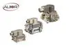
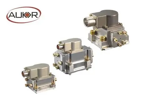
Model: F-series Dual-Nozzle Baffle Force Feedback Electro-hydraulic Flow Servo Valve Product Features: • F02 replaces MOOG's 31 series • F06 replaces MOOG's 760 series • F07 replaces MOOG's 760 series • High control precision, fast dynamic response, and easy operation • All-stainless steel housing, high structural strength • Compact internal structure, small size, and light weight • Stable working performance, high reliability, and long service life • Low internal leakage and low power consumption • Low hysteresis, high resolution, and high repeatability • Good linearity, large driving force, and low zero drift Product Applications: • Remote-controlled vehicles • Automated guided vehicles • Automation devices • Robots • Downhole tools Working Principle: The F-series dual-nozzle baffle force feedback electro-hydraulic flow servo valve (referred to as electro-hydraulic servo valve) uses a permanent magnet torque motor, which consists of two permanent magnets, an armature assembly, upper and lower magnetic conductors, and two coils. The permanent magnets generate polarized magnetic flux, which is installed parallel between the upper and lower magnetic conductors. The armature assembly, consisting of an armature, baffle, Bourdon tube, and feedback rod, is fixed to the housing after being connected together. Both ends of the armature extend into the air gap of the magnetic flux circuit. The Bourdon tube provides elastic support and sealing for the armature baffle. The baffle of the first-stage hydraulic amplifier extends from the Bourdon tube and is inserted between the two nozzles. Hydraulic oil flows through an internal oil filter, two fixed throttling orifices, and then out through a variable throttling orifice between the nozzle and baffle. The pressure in the two nozzle chambers acts on both ends of the second-stage valve core. The second stage of the servo valve uses a standard four-way spool valve, with the feedback rod extending from the baffle and inserted into a small slot in the middle of the valve core. When a control current is input to the torque motor coil, a torque is generated on the armature due to the interaction between the control magnetic flux and the polarization magnetic flux. This torque causes the armature assembly to rotate around the rotation center of the Bourdon tube, thereby moving the baffle. This causes the variable throttling area of the nozzle-baffle on one side to decrease, while the variable throttling area on the other side increases, resulting in a pressure difference in the nozzle chamber and causing valve core displacement. This displacement continues until the feedback torque generated by the bending of the feedback rod balances the torque generated by the control current, at which point the baffle is approximately in the neutral position. Since the torque of the torque motor is basically proportional to the control current supplied to the valve, the feedback torque is proportional to the valve core displacement. When the pressure drop of the servo valve is constant, the output flow rate is proportional to the input control current. Product Dimensions: 69x43x107mm (F02), 99x56x131mm (F06), 99x56x131mm (F07) Mounting Interface Standards: ISO 10372-02-02-0-92 (F02), ISO 4401:2005 (F06, F07) Vibration Resistance: 3-axis, 30g, 10-2000Hz Operating Temperature: -20 … +60℃ Storage Temperature: -40 … +80℃ Ambient Temperature: -55 … +150℃ Oil Temperature: -55 … +120℃ Weight: 400g (F02), 1200g (F06), 1400g (F07) Maximum Operating Pressure: 280Bar Rated Current: 15-40mA Coil Resistance: 80-200Ω Hysteresis: <4% Resolution: <1% Linearity: <7.5% Symmetry: <10% Pressure Gain: >30% Zero Deviation: <3% Overlap: <2.5% Supply Pressure Zero Drift (80%~110%) Ps: <2% Return Pressure Zero Drift (0~20%) Ps: <2% Temperature Zero Drift (-30~+150℃): <4% Frequency Response - Amplitude Bandwidth (-3dB): >50% Frequency Response - Phase Bandwidth (-90°): >50% Insulation Resistance: >50MΩ Hydraulic Oil: DIN52524-Part 1 ...Part 3 / ISO11158 Recommended Viscosity: 15-100cSt Permissible Viscosity: 5-400cSt QN/Rated Flow Rate, per Throttling Edge ΔP=35 bar: 2L/min, 5L/min, 10L/min, 15L/min, 20L/min, 30L/min, 63L/min, 100L/min Internal leakage at 210 bar: 0.6-1.7L/min (F02), <3L/min (F06, F07) Cleanliness level recommended according to ISO 4406 for functional safety: 18 / 15 / 12 Recommended cleanliness level conforming to ISO 4406 for longer service life: 17 / 14 / 11 Command signal: +/- 10V, +/- 10mA, 4...20mA Valve core and sleeve design: C: 4-way, zero overlay, linear characteristics
- Dual-nozzle baffle force feedback servo valve
Production Capacity:
10000
Delivery Timeframe:
Within 30 Days
Incoterms:
CFR - Cost and Freight
CIF - Cost, Insurance and Freight
CIP - Carriage and Insurance Paid to
CPT - Carriage Paid to
DAF - Delivered At Frontier
DDP - Delivered Duty Paid
DDU - Delivered Duty Unpaid
DEQ - Delivered Ex Quay
DES - Delivered Ex Ship
EXW - Ex Works
FAS - Free Along Ship
FCA - Free Carrier
FOB - Free on Board
Packaging Details:
Wooden Box
More about
NINGBO AUKOR ELECTRO-HYDRAULIC TECHNOLOGY CO.,LTD
200-500
Employees
1M - 2M
Sales volume (USD)
60%
% Export sales
Year
Established
Business type
- Industry / Manufacturer
Keywords
- Servo valves
- servo actuators
Contact and location
-
 Karry ********
-
+86 1********
-
Ningbo / | China
