
Description
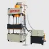
(I) This machine has an independent power mechanism and electrical system, and can be operated in both adjustable and semi-automatic modes. The working pressure and slide stroke range of this machine can be adjusted according to process requirements; and it can complete both constant pressure and constant stroke molding processes. (II) Press operation program: Manual: 1. The control button can start and stop the motor. 2. The start button can raise the upper die independently, stopping at any position within the stroke, and stopping when it hits the proximity switch. 3. The start button can lower the upper die independently, stopping at any position within the stroke, and stopping when the upper die falls to the middle die and the pressure gauge reaches the set pressure. 4. The start button can eject the lower die independently, stopping at any position within the stroke, and stopping when it hits the proximity switch. 5. The start button can retract the upper die independently, stopping at any position within the stroke, and stopping when it hits the proximity switch. 6. Emergency stop button is set. 7. Automatic start is set to start the automatic program. 8. Manual and automatic switching is possible. Automatic: 1. Initial position: The upper die rises to the set position, and the lower die descends to the set position of the cavity. 2. Manually fill the mold with material, then switch to automatic mode and start the automatic program. The upper mold will descend and begin the automatic program. 3. The upper mold contacts the upper surface of the middle mold, then pressure is applied until a certain level is reached and stopped (controlled by an electrical contact pressure gauge). 4. The lower mold rises to begin molding (the rising speed can be adjusted via a manual stop valve), rising to the set position (product specification), and holding pressure (the holding time is adjustable). 5. After holding pressure, the upper mold rises to the set position, and the lower mold rises. 6. The lower mold rises to the ejection position and stops (the pause time between the lower mold and the ejection position is adjustable). 7. The lower mold returns to the material feeding position, then material is added, and the automatic program is restarted, repeating the entire operation. Model: YZ32-500T Nominal Force: 5000KN Maximum Hydraulic System Pressure: 25MPa Slide Opening Height: 1500mm Slide Stroke: 500mm Internal Column Dimensions (Left/Right × Front/Back): 1200mm × 1000mm Slide Working Idle Speed: 34mm/s Slide Working Return Speed: 72mm/s Center Distance of T-Slots on Upper and Lower Worktables: 500mm Upper T-Slot Width: 18mm Motor: 11KW Oil Pump: 40YCY Integrated Cartridge Valve: YZY32-500FNCV00 Four-Column Diameter: Φ140mm All parameters can be customized according to actual processes. II. Structural Overview: This machine consists of two main parts: the main unit and the control mechanism, connected by pipelines and electrical devices to form a whole. The main unit includes the machine body, main cylinder, and stroke limiting device. The control mechanism includes the hydraulic pump station (power system), electrical box, and mobile control panel. The structure and function of each component are described below: 1. Main Body: The main body adopts a four-beam, four-column structure, consisting of an upper crossbeam, slider, worktable, column, main cylinder, hydraulic power system, and electrical system. 2. Main Cylinder: The main cylinder body is fixed to the cylinder cap. The lower end of the piston is connected to the slider with connecting flange bolts. The piston head has YX-type sealing rings in opposite directions, and an O-ring is installed on the piston rod, dividing the cylinder into two oil chambers. A guide band is installed on the cylinder, and the cylinder port is sealed by the cylinder flange and bolts. A dustproof ring is installed on the cylinder port flange to ensure dust protection for the piston rod. 3. Hydraulic Station: The hydraulic pump consists of an oil tank, axial piston pump, electric motor, two-way cartridge valve, oil filter, and air filter. The oil tank is a welded part of Q235 steel plate, with a pressure gauge at the front end for pressure observation and adjustment. A level gauge is installed below the pressure gauge bracket for level observation. An oil suction filter is installed at the oil pump's suction port to ensure the cleanliness of the pump and hydraulic system. An air filter is installed on the oil tank panel to filter air. The top cover can be opened for refueling, and the cover can be removed for cleaning the oil tank. The axial piston pump hydraulic system uses a YCY14-1B axial piston pump. For details, please refer to the axial piston pump instruction manual; it will not be summarized here. III. The cartridge valve's structure mainly consists of a cartridge, control cover, pilot control valve, and integrated valve block. 1. The cartridge consists of valve components, springs, seals, and a valve sleeve. It can be a cone valve or a spool valve. Its main function is to control the direction, pressure, and flow rate of oil in the oil circuit. 2. The control cover consists of various miniature pilot control elements and other components embedded within the cover. Its main function is to fix the cartridge. The embedded miniature pilot control elements, combined with the pilot control valve, can control the working state of the cartridge valve. The control cover is divided into directional control cover, pressure control cover, and flow control cover. 3. The pilot control valve is mounted on the control cover and is a small-diameter solenoid directional valve that controls the movement of the insert. Its components are standard solenoid directional valves. 4. The integrated valve block is used to install the insert, control cover, and other control valves, connecting the main oil circuit and the control oil circuit. IV. Overview of the Hydraulic System The hydraulic system consists of energy conversion devices (pumps and cylinders) and energy transmission devices (tank, pipelines), etc. With the help of electrical system control, the slider is driven to complete various action cycles. The hydraulic system uses high-flow cartridge valves, and an oil suction filter is installed at the pump inlet to prevent impurities from entering the hydraulic system and ensure the normal operation of the oil circuit. The system includes oil temperature and level displays, air filters, etc. The oil tank is a welded steel plate structure with drain and sludge plugs at the bottom.
- Hydraulic press
- press machine
- oil press
- four-column hydraulic press
Production Capacity:
150
Delivery Timeframe:
Within 60 Days
Incoterms:
FOB - Free on Board
Packaging Details:
Not informed
More about
Shandong congou Machine Tool Co., Ltd
50-100
Employees
500K - 1M
Sales volume (USD)
60%
% Export sales
Year
Established
Business type
- Industry / Manufacturer
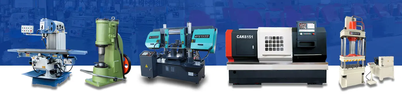
Keywords
- Band saws
- hydraulic presses
- milling machines
- lathes
- slotting machines
- air hammers
- grinding machines
- drilling machines
- Congou machine tools Ver Mais
Contact and location
-
 Leo ********
-
+86 1********
-
枣庄 / 山东 | China
You might also be interested
-
500-ton Three-Beam Four-Column Hydraulic Press for Metal Stretch Forming and Shaping (customization available)
(I) This machine has an independent power mechanism and electrical system, and can be operated in both adjustable and se
-
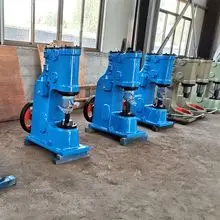
25/40/75/150kg Blacksmith Forging Air Hammer
I. Machine Tool Model and Name 1. Model: C41-75kg 2. Name: Integrated Air Hammer 3. The machine tool color is the compan
-
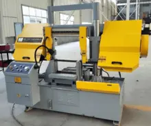
GH400 Horizontal Double-Column Metal Band Saw with Center Travel
GH400 Horizontal Double-Column Metal Band Saw (Intermediate Saw) I. Main Applications: The GH400 horizontal band saw is
-
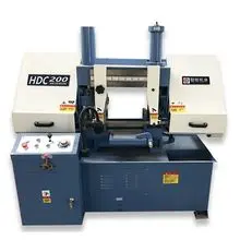
HDC200 Horizontal Double Column Metal Band Saw for Small Profiles
1. Main Application The HDC200 horizontal band saw is designed for efficient cutting of small to medium profiles, compat
-
HDC280 Horizontal Double Column Metal Band Saw for Medium Profiles
1. Main Application The HDC280 horizontal band saw is designed for efficient cutting of medium profiles, compatible with
-
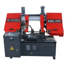
HDC300 Horizontal Double Column Metal Band Saw for Medium & Large Profiles
1. Main Application The HDC300 horizontal band saw is designed for efficient cutting of medium to large profiles, compat
-
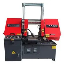
HDC320 Horizontal Double Column Metal Band Saw for Medium-Large Profiles
1. Main Application The HDC320 horizontal band saw is designed for efficient cutting of medium to large profiles, compat
-
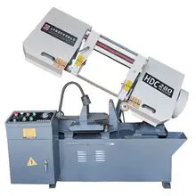
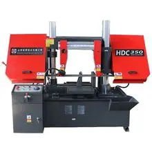
HDC350 Horizontal Double Column Metal Band Saw for Large Section Profiles
1. Main Application The HDC350 horizontal band saw is designed for efficient cutting of large section profiles, compatib
-
C41-16kg Mini Pneumatic Forging Hammer | Compact Power Hammer for Hobbyist
I. Overview The C41-16kg is a compact, self-contained air hammer designed specifically for hobbyists and small-scale for
-
C41-25kg Self-contained Pneumatic Forging Hammer | One-piece Power Hammer for Blacksmith
I. Overview The C41-25kg one-piece air hammer is the most popular choice for artistic blacksmiths and knife makers world